MC Stepup TransformerT-550
A phono-balanced transmission supported step-up transformer for high sound quality of the MC cartridge draws out the music’s reality and the artist’s passion
Recieved Prizes
"Audio Accessory" Magazine / Ongen PublishingAudio Excellence Award Y2021 Bronze Award
"MJ Musen to Jikken" magazine / SEIBUNDO SHINKOSHA PublishingMJ Technology of the Year 2020 Analog Components Award
"Analog" magazine / Ongen PublishingAnalog Grand Prix Gold Award in Y2021
"Stereo" magazine / Ongaku no Tomo shaBest Buy Components; Number 2 Analog product in Y2020
"Stereo" magazine / Ongaku no Tomo shaBest Buy Components; Number 3 Analog product in Y2021
Product Outline and Concept
We are pursuing concepts such as the magnetic flux control technology and the mounting structure of the transformer that was cultivated in the T-1000 released in 2019 which had won many awards. We adopted a 10mm thick aluminum slant panel which was used in the new generation models such as the EA-350 and was designed in the same accordance. We will release the MC step-up transformer, T 550, which brings about spatial expression having abounding information. This was difficult in the conventional products.
Main feature
Adopting a strong chassis structure that follows the T-1000 design
The front panel is a rigid box structure having a 10mm thick slanted aluminum panel, a 1.2mm thick copper plating board chassis, and a 1.6mm thick copper plating cover. Non-magnetic stainless steel screws are used for assembly to ensure rigidity and reduce magnetic distortion.
In addition, the transformer itself is floating on the main unit with a high damping rubber material and prevents the transmission of external vibrations.
Also electrically speaking, by placing a magnetic shield material near the transformer can bring about the reduction of external induction hums and magnetic distortion. v
The Input Portion Supporting a Phono Balanced Transmission
When generating power through a cartridge coil, a balanced operation is conducted essentially. Transmitting this signal with an unbalanced connection results in not only losing the worth of a balanced type, but also the sound quality is directly affected by external noises.
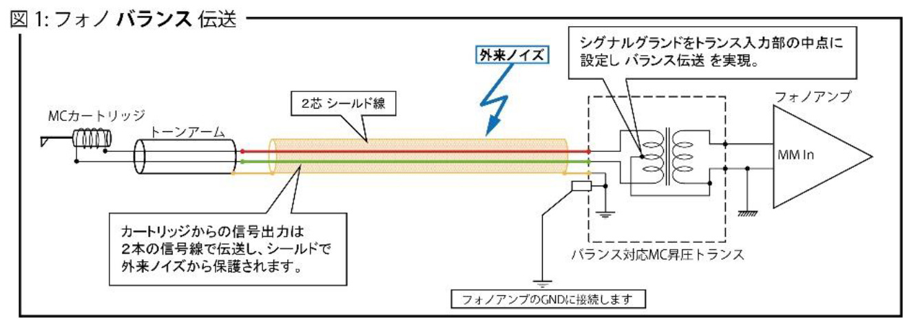
The basis of wiring connections by using a balanced phono cable due to a 2-core shield wire is shown in Fig.1. The signal is transmitted from the cartridge coil to the transformer coil through the pushpull balancing circuit and the shield-earth covers it and therefore, the effects caused by external noises can be blocked.
In addition, a full balanced connection (No.2 pin hot) is structured on the cartridge side because the center of the input part of the transformer is connected to the signal GND of the output part.
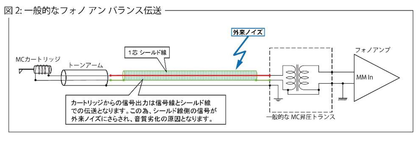
A general structure of connecting a step-up transformer for an MC cartridge to an unbalanced phono cable is shown in Fig. 2. At the unbalanced connection | composed of the signal wire and external shield, the shield side is exposed to the external noises.
Therefore, it results in not only to be easily effected by the noises, but the signal wire also being invaded by the negative effects.
MC step-up transformer due to a special split winding structure developed by us.
We adopted our original divided winding wire structure. By winding a low-loss ultra-thick copper wire around a large EI core made of a 0.2mm thick 78% permalloy material, we brought into effect an outstanding frequency characteristic and phase characteristic at a wide band. This achieves outstanding characteristics of excellent linearity for low frequency and high-efficiency gain which reduces phase distortion in the audible band range and brings about a threadlike spatial expression and clearer sound image localization that can fill vitality over the entire range.
Adoption of Parts With High Sound Quality
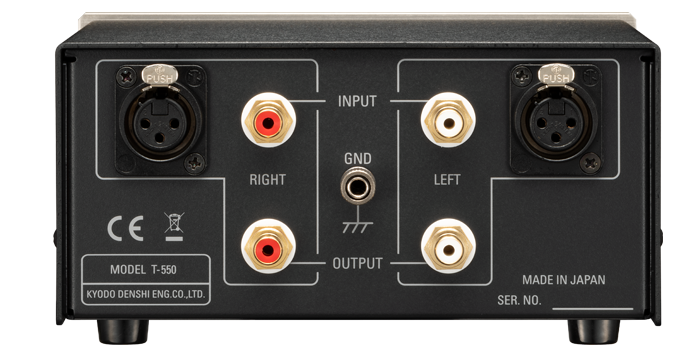
We adopted carved gold-plated terminals for the input/output terminals.
Caution
- The XLR or RCA, only one can be used for the input. If two are used at the same time, it can be the cause for noises to generate.
- This device is designed for a balanced connection due to a 2-core shielded wire.
Product Specification
| Best Cartridge’s Output Impedance*1 |
1.5 – 40 ohms |
| Load Impedance |
47k ohms |
| Gain |
26dB |
| Frequency Range |
10 – 50kHz (+2dB) |
| Frequency |
Response |
| Dimensions |
W: 174 x H: 90 x D: 173 |
| Weight |
2.1kg |
| Input / Output Terminals (XLR, RCA) |
Gold Plated Terminals |
*1: The cartridge that can be used has an output impedance of 1.5 – 40 ohms.